Let me get on my soap box for a minute….
Programming Microcontrollers twenty five years ago was tough. You had to buy expensive programmers, find the right microcontroller, learn a bunch of machine code, and then write anything you wanted to do from scratch. You’d need to buy power supply chips, driver chips, the right resistors, capacitors and diodes… Then you had to make a printed circuit board to wire everything up, with required expensive software, and time, and revisions to get it working. So, you’d only embark on this journey if you had a specific project you wanted to do, and a lot of time and money to do it.
Arduino changed that, completely. The hardware is almost free. If you attended the WOPR0x01, it’s COMPLETELY FREE!!!! It includes so many features on the board that you can probably find a way to get your problem solved without buying any additional hardware. The software contains awesome examples of code for you to start with, and modify to do what you need. And, because the software is so friendly, and the hardware so cheap, there are gobs of people using it. And they LOVE to share their code and tutorials with you!
There really isn’t any excuse anymore to keep you from spitting out cool little electronic gadgets. Go Build!!!
Step One is to read through an introduction to the Arduino, and to get (FREE) software to interface and program your Arduino UNO board.
The best resources come from the Arduino company itself, who does a wonderful job of supporting this product with tutorials, libraries, and software, all completely open source. Start here: https://www.arduino.cc/en/Guide/HomePage
Really, to get started with Arduino, once you can get the arduino talking to your computer, you can spend a lot of time just going through all of the examples pre-loaded into the software. Start modifying those examples to do fun stuff, and jump right in!

Once you’ve gotten through the introduction, and have installed the IDE, you’re ready to start coding! The Arduino is the hacker’s dream! Included in the IDE software you just installed are numerous examples built-in for you to try, and then to modify and combine to make more complex projects! They have online guides, showing the proper way to connect any necessary hardware and wiring. Check out the examples!
Your WOPR 0x01 kit includes the following:
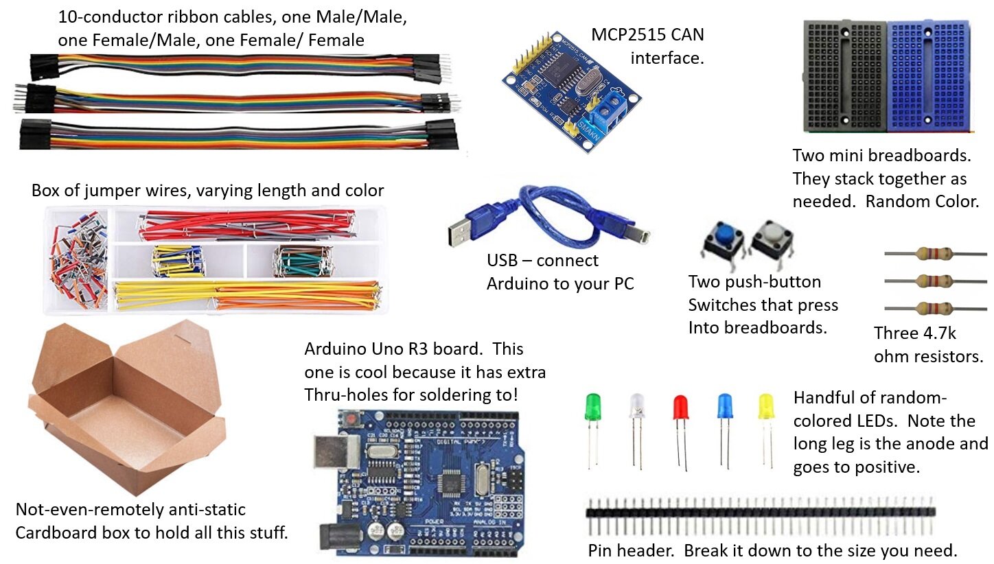

- Two mini, connectable breadboards are included. The image highlights electrical connections: the five blue highlighted ports are electrically connected to each other, but do not electrically connect to the five reds, or five yellows. Each row of five ports electrically connect to each other, but to no other pins in the breadboard.

Bend the pins down on the LCD interface board, to nearly vertical. This will allow it to easily plug into the breadboard.
Plug the LCD and the MCP2515 CAN interface into the breadboard as shown. Use your Male/Male pin ribbon cables to connect everything to the Arduino as shown. Use some jumper wires from your wire kit to connect the ground and VCC(/power/+5V) from the LCD to the CAN interface board: they can share power and ground.


The MCP-2515 - based CAN interface can be connected to the Arduino Uno as shown here. (Color coding to easily match the male/female rainbow ribbon cable included with your kit). Note that this version of the MCP2515 board uses an 8MHz crystal oscillator chip for the clock, which defines “time” for the device. A very good library supporting the MCP2515 can be found here, but assumes that the chip is a 16MHz version. You’ll need to either use a different library built for the 8MHz chip, or send and extra argument specifying a non-standard clock speed at initialization in your code (super-easy), or desolder the 8MHz and install a 16MHz crystal. For the Chevy Volt example, we’re going to use a modified library that has a patch built-in for you already.

I peeled the adhesive covering off of one of the breadboards and stuck it right to the back of the Arduino. This really holds everything together pretty well to take out to the car, yet lets you take parts off at a later date. The breadboard stays on the Arduino for life after that, but it’s helpful.


Lastly, connect the OBD-II cable to the CAN interface board as shown. On your cable, green is the CAN-Low and White is the CAN-High. This cable is made of ethernet cable, which makes good CAN cable in a pinch, because it’s twisted-pair.
Super! You’re almost ready to go! Go get the library file (mcp_can) we’re going to use for the mcp2515 CAN board, and install it into your library folder in your Arduino directory. It has some great examples you can test out, and modify to learn more about using this device. We’re going to use a modified version of this, so email me at jeremy.nethercutt@nethercuttsolutions.com, and I’ll email it to you!
And here is some simple code that will display the steering wheel position and accelerator pedal position. Note that most of it is commented-out (the “//” at the front of a line tell the compiler to ignore everything on that line. That’s useful when leaving documentation notes in your code, as well as deactivating features you don’t want to use, but may want to leave in code to reactivate at a later revision of software. Some of the deactivated code below can be used with a digital to analog converter to make a varying voltage output. I use that on my throttle pedal controller to drive trucks on my dyno, where the control computer sends accelerator pedal commands via CAN messages.
With this code programmed into your Arduino, the LCD should come up and start showing you steering wheel position and accelerator pedal position, even while the car isn’t moving. These are “raw” CAN messages, not OBD-II messages. The Arduino doens’t have to sent anything to the car to get the messages: the Volt simply broadcasts these messages (and many others) periodically.
// CAN Interface for Chevy Volt
// Jeremy Nethercut, Nethercutt Solutions Inc. 4/21/2020 // jeremy.nethercutt@nethercuttsolutions.com , V1.0
#include <Wire.h>
//#include <Adafruit_MCP4725.h> for MCP4725 digital to analog converter.
#include <mcp_can.h>
#include <SPI.h>
#include <LCD.h>
#include <LiquidCrystal_I2C.h>
//Adafruit_MCP4725 dac1; //These initialize a MCP4725 digital to analog converter if you add one. //Adafruit_MCP4725 dac2; //
LiquidCrystal_I2C lcd(0x27,2,1,0,4,5,6,7); // 0x27 is the I2C bus address for an unmodified backpack
//this code is for DAC.. //float voltage_output1; //float voltage_output2; //uint32_t dac1_value; //uint32_t dac2_value; //... this code is for DAC.
const int buttonPin = 4; // input pin for pushbutton
int timeout = 0; //counter for timeout safety
int timeoutlimit = 10;//how many loops until the CAN message is lost, and should be reset to zero.
int watchdog = 0;
int watchdoglimit=100;
int angle=0;
int accel=0;
int stopvolt=0;
//const byte interruptPin = 0;
volatile unsigned char flagRecv = 0;
unsigned char len = 0;
unsigned char buf[8];
char str[20];
int counter = 0;
//float dynospeed=0; //float dynospeedscaling = 2.55; //float pedalvoltage = 0; //float pedalvoltagescaling = 655; //float testtime=0; //float testtimescaling = 5; //float throttlecmd=0; //int progress = 0;
volatile unsigned char stmp[8] = {0xFE, 0xED, 0xFA, 0xCE, 0xC0, 0xFF, 0xEE, 0x00};
void setup()
{
pinMode(buttonPin, INPUT);
timeout=0;
watchdog=0;
Serial.begin(9600);
// init can bus, baudrate: 250k
if(CAN.begin(12) ==CAN_OK) Serial.print("can init ok!!\r\n"); // the (12) is a special case for this CAN interface for the Chevy volt. It needs to run at 500kBPS...
//but the oscillator on the board is an 8MHz, and the default MCP2515 library assumes 16MHz. A little hacking is required... that's why you need to use the specific
//CAN library.
else {Serial.print("Can init fail!!\r\n");}
//attachInterrupt(digitalPinToInterrupt(interruptPin), MCP2515_ISR, FALLING); // start interrupt
//attachInterrupt(0, MCP2515_ISR, FALLING);
CAN.init_Mask(0, 0, 0xfff); // there are 2 mask in mcp2515, you need to set both of them CAN.init_Mask(1, 0, 0xfff);
//dac1.begin(0x60);
//dac2.begin(0x61);
//Set output to zero volts, to initialize the voltage to an appropriate value at startup, before CAN messages, or in the event of no CAN message.
//pedalvoltage=0;
//voltage_output1 = pedalvoltage * 4 / 5.0 + 0.5; // output 1 in volts 0.5~4.4
//dac1_value = int((voltage_output1 / 5) * 4096);
//dac1.setVoltage(dac1_value,false);
//Serial.println("initialize output to 0% throttle before CAN message received.");
// activate LCD module
lcd.begin (16,2); // for 16x2 LCD module
lcd.setBacklightPin(3,POSITIVE);
lcd.setBacklight(HIGH);
lcd.home (); // set cursor to 0,0
lcd.print("Chevy Volt Hacking!");
lcd.setCursor (0,1);
// go to start of 2nd line
lcd.print("init: ");
int j=0;
for(j=0;j<6;j++){ data-preserve-html-node="true"
lcd.print(".");

delay(30);
}
lcd.print("DONE");
delay(100);
lcd.clear();
delay(100);
lcd.home();
lcd.print("init CAN:");
delay(40);
lcd.print(".OK.500k");
delay(100);
lcd.setCursor (0,1);
lcd.print("Begin Broadcast");
delay(50);
lcd.print(".");
delay(100);
lcd.print("OK");
delay(100);
lcd.clear();
lcd.setBacklight(LOW); // Backlight off
delay(25);
lcd.setBacklight(HIGH); // Backlight on
lcd.home (); // set cursor to 0,0
lcd.print("Waiting for");
lcd.setCursor (0,1); // go to start of 2nd line
lcd.print("0x1E5,0x0AA msg");
// // set filter, we can receive id from 0x04 ~ 0x09 // //CAN.init_Filt(0, 0, 0x255); // there are 6 filter in mcp2515
CAN.init_Filt(1, 0, 0x1E5); // there are 6 filter in mcp2515
//CAN.init_Filt(2, 0, 0x0AA); // there are 6 filter in mcp2515
//CAN.init_Filt(3, 0, 0x07); // there are 6 filter in mcp2515
//CAN.init_Filt(4, 0, 0x08); // there are 6 filter in mcp2515
//CAN.init_Filt(5, 0, 0x09); // there are 6 filter in mcp2515
}
void MCP2515_ISR()
{
flagRecv = 1;}
void loop()
{
//counter++;
//stmp[7] = counter;
//timeout++;
//watchdog++;
//stopvolt = digitalRead(buttonPin);
//if(stopvolt==1){
// Serial.println("Making the Volt stop working now...");
// lcd.clear();
// lcd.home (); // set cursor to 0,0
// lcd.print("Stoppin Volt now. ");
// CAN.sendMsgBuf(0x0AA, 0, 8, stmp); //
// delay(10);
// send data per 100ms it's 75ms delay becaues the serial writes take a lot of time at 9600 bps
//}
if (CAN_MSGAVAIL == CAN.checkReceive()) // check if get data
{


  //  flagRecv = 0;                // clear flag

    CAN.readMsgBuf(&len, buf);
    // read data,  len: data length, buf: data buf


   // Serial.println("\r\n------------------------------------------------------------------");

   // Serial.print("Get Data From id: ");

   // Serial.println(CAN.getCanId());

   // for(int i = 0; i<len; i++)    // print the data

   // {

   //     Serial.print("0x");

   //     Serial.print(buf[i], HEX);

   //     Serial.print("\t");

   // }

   // Serial.println();


   if(CAN.getCanId()==0x1E5){

    angle = (buf[1]*256+buf[2])/256;

    //Serial.print(buf[1]);

    //Serial.print(" ");

    //Serial.print(buf[2]);

    //Serial.println(" Angle");

    CAN.init_Filt(1, 0, 0x0AA);
    //this is a hack to make sure I get the other message next.  otherwise, the angle message comes in at such a high frequency, that the accel pedal hardly ever gets updated.

    delay(2);

    }

   if(CAN.getCanId()==0x0AA){

    accel = (buf[7]*100/255);

    //Serial.print(buf[7]);

    //Serial.println(" Accel");

   CAN.init_Filt(1, 0, 0x1E5);

   delay(2);


   }
// if(watchdog > watchdoglimit){
// watchdog = watchdoglimit;
// setup();
// }
//  Serial.print("Test Time (s):");

  //  Serial.print(testtime);

  //  Serial.print("   Dyno Speed (mph):");

  //  Serial.print(dynospeed);

  //  Serial.print("   Throttle Cmd:");

  //  Serial.print(throttlecmd);

  //  Serial.print("   Pedal Voltage (V):");

  //  Serial.print(pedalvoltage);

  //  Serial.print("  Timeout:");

  //  Serial.print(timeout);

  //voltage_output1 = pedalvoltage * 4 / 5.0 + 0.5; // output 1 in volts 0.5~4.4

  //if(voltage_output1 < 0.5){voltage_output1 = 0.5;}

  //if(voltage_output1 > 4.5){voltage_output1 = 4.5;}

  //voltage_output2 = pedalvoltage * 2 / 5.0 + 0.25;
  // output 2 in volts 0.25~2.17

  //dac1_value = int((voltage_output1 / 5) * 4096);

  //dac2_value = int((voltage_output2 / 5) * 4096);

  //dac1.setVoltage(dac1_value,false);

  //dac2.setVoltage(dac2_value,false);

  //Serial.print("DAC1 Out:");

  //Serial.println(dac1_value/800.0);

  //Serial.print("V,  DAC2 Out:");

  //Serial.print(dac2_value/800.0);

  //Serial.println(" V.");


  lcd.clear();

  lcd.home(); // set cursor to 0,0

  lcd.print("Accel: ");

  lcd.print(accel);

  lcd.setCursor (0,1);        // go to start of 2nd line

  lcd.print("Steering: ");

  lcd.print(angle);

  delay(5);


}
}
/* END FILE */