Let me get on my soap box for a minute….
Programming Microcontrollers twenty five years ago was tough. You had to buy expensive programmers, find the right microcontroller, learn a bunch of machine code, and then write anything you wanted to do from scratch. You’d need to buy power supply chips, driver chips, the right resistors, capacitors and diodes… Then you had to make a printed circuit board to wire everything up, with required expensive software, and time, and revisions to get it working. So, you’d only embark on this journey if you had a specific project you wanted to do, and a lot of time and money to do it.
Arduino changed that, completely. The hardware is almost free. If you attended the WOPR0x01, it’s COMPLETELY FREE!!!! It includes so many features on the board that you can probably find a way to get your problem solved without buying any additional hardware. The software contains awesome examples of code for you to start with, and modify to do what you need. And, because the software is so friendly, and the hardware so cheap, there are gobs of people using it. And they LOVE to share their code and tutorials with you!
There really isn’t any excuse anymore to keep you from spitting out cool little electronic gadgets. Go Build!!!
Step One is to read through an introduction to the Arduino, and to get (FREE) software to interface and program your Arduino UNO board.
The best resources come from the Arduino company itself, who does a wonderful job of supporting this product with tutorials, libraries, and software, all completely open source. Start here: https://www.arduino.cc/en/Guide/HomePage
Really, to get started with Arduino, once you can get the arduino talking to your computer, you can spend a lot of time just going through all of the examples pre-loaded into the software. Start modifying those examples to do fun stuff, and jump right in!

Once you’ve gotten through the introduction, and have installed the IDE, you’re ready to start coding! The Arduino is the hacker’s dream! Included in the IDE software you just installed are numerous examples built-in for you to try, and then to modify and combine to make more complex projects! They have online guides, showing the proper way to connect any necessary hardware and wiring. Check out the examples!
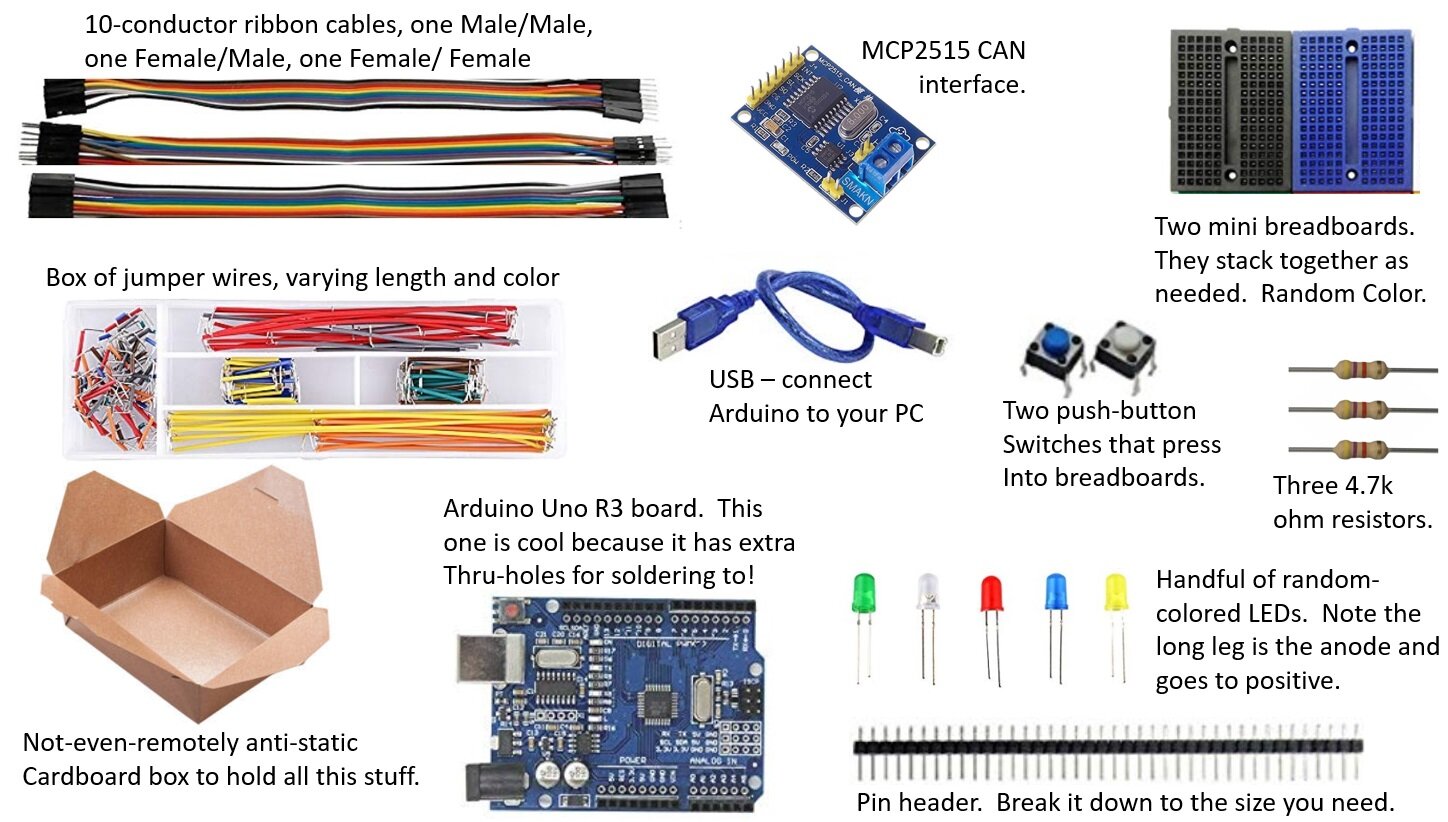
Your WOPR 0x01 kit includes the following:

- Two mini, connectable breadboards are included. The image highlights electrical connections: the five blue highlighted ports are electrically connected to each other, but do not electrically connect to the five reds, or five yellows. Each row of five ports electrically connect to each other, but to no other pins in the breadboard.

The MCP-2515 - based CAN interface can be connected to the Arduino Uno as shown here. (Color coding to easily match the male/female rainbow ribbon cable included with your kit). Note that this version of the MCP2515 board uses an 8MHz crystal oscillator chip for the clock, which defines “time” for the device. A very good library supporting the MCP2515 can be found here, but assumes that the chip is a 16MHz version. You’ll need to either use a different library built for the 8MHz chip, or send and extra argument specifying a non-standard clock speed at initialization in your code (super-easy), or desolder the 8MHz and install a 16MHz crystal.
Super! You’re almost ready to go! Go get the library file (mcp_can) we’re going to use for the mcp2515 CAN board, and install it into your library folder in your Arduino directory. It has some great examples you can test out, and modify to learn more about using this device. https://github.com/Seeed-Studio/CAN_BUS_Shield
And here is some simple code to get that MCP2515 doing something! Hook it up with your friend, and get some messages bouncing back and forth!
// WOPR Summit CAN MCP2515 example
// Jeremy Nethercutt
// jeremy.nethercutt@gmail.com
// 11/24/19
#include <mcp_can.h>
#include <SPI.h>
const byte interruptPin = 0;
volatile unsigned char flagRecv = 0;
unsigned char len = 0;
unsigned char buf[8];
char str[20];
int counter = 0;
int unlocked = 0;
int j=0;
unsigned char CTF_flag[8] = {0x0 ,0x1, 0x2, 0x3, 0x4, 0x5, 0x6, 0x7};
volatile unsigned char stmp[6] = {0xDE, 0xAD, 0x00, 0x00, 0xBE, 0xEF};
unsigned char mod_buf[8];
void setup()
{
Serial.begin(9600);
//initialize serial communiation, so you can read your Serial.print lines in your serial terminal on your computer for debugging.
//if you get serious about making this code efficient, or keeping up with fast CAN messages, you'll want to speed up
// this serial communication speed: it takes too long to transmit serial at this low of a speed.
if(CAN.begin(CAN_500KBPS) ==CAN_OK) Serial.print("WOPR 0x01. CAN init ok!!\r\n");
// init can bus, baudrate: 250k Note the command here is twice as fast as the baud you want,
// because the version of the MCP2515 board you have is using an 8MHz chip, instead of the standard
// 16MHz chip. This is the easies fix to that problem.
else Serial.print("Can init fail!!\r\n");
// if you're getting this failure, you've likely miswired something.
//attachInterrupt(digitalPinToInterrupt(interruptPin), MCP2515_ISR, FALLING);
// start interrupt
//attachInterrupt(0, MCP2515_ISR, FALLING);
// uncomment the above lines to experiment with interrupts: things that happen when you recive a message.
//CAN.init_Mask(0, 0, 0xfff);
// there are 2 mask in mcp2515, you need to set both of them
//CAN.init_Mask(1, 0, 0xfff);
// you can comment out the above, as well as the Filters below, to only use certain message IDs.
//set filter, we can receive id from 0x04 ~ 0x09
//CAN.init_Filt(0, 0, 0x044); // there are 6 filter in mcp2515
//CAN.init_Filt(1, 0, 0x7ff); // there are 6 filter in mcp2515
//CAN.init_Filt(2, 0, 0x06); // there are 6 filter in mcp2515
//CAN.init_Filt(3, 0, 0x07); // there are 6 filter in mcp2515
//CAN.init_Filt(4, 0, 0x08); // there are 6 filter in mcp2515
//CAN.init_Filt(5, 0, 0x09); // there are 6 filter in mcp2515
// you can uncomment out some of the above, if you are only interested in looking at specific messages. }
void MCP2515_ISR() { flagRecv = 1; }
void loop()
{
CAN.sendMsgBuf(0x43, 0, 6, stmp); //send heartbeat to let people know I'm here.
delay(98); // send data per 100ms. (code execution takes about 2ms in this example)
if (CAN_MSGAVAIL == CAN.checkReceive())
// check if get data
{
//  flagRecv = 0;                // clear flag

    CAN.readMsgBuf(&len, buf);    // read data,  len: data length, buf: data buf
    mod_buf[0]=buf[0]+1;
    mod_buf[1]=buf[1];
    mod_buf[2]=buf[2];
    mod_buf[3]=buf[3];
    mod_buf[4]=buf[4];
    mod_buf[5]=buf[5];
    mod_buf[6]=buf[6];
    mod_buf[7]=buf[7];

    CAN.sendMsgBuf(0x100, 0, len, mod_buf);
    // whatever message gets received on the CAN bus, this will add 1 to the first byte, then resend the data under a new
    // CANid=0x100.

    Serial.print("  Buff length:");
    Serial.println(len);


}
}
/* END FILE */